Capacitor Bank Working Principle Pdf
For high voltage applications numbers of capacitor units are connected in series and parallel combinations to form a capacitor bank for required voltage and Kilo VAR ratings. But typically externally fused capacitor banks have higher failure voltages and currents than fuseless or internally fused banks because an external fuse blowing causes the loss of an entire unit.

Testing Of Capacitor Bank Electrical4u
Then q α V or.

. In transformers and electric motors capacitor banks are used to correct power-factor lag or phase shift in alternating-current AC power supplies. The arrangement of these can be done at substation or power plants. To demonstrate how does a capacitor work let us consider a most basic structure of a capacitorIt is made of two parallel conducting plates separated by a dielectric that is parallel plate capacitorWhen we connect a battery DC Voltage Source across the capacitor one plate plate-I gets attached to the positive end and another plate plate-II to the negative end of the.
A capacitor can have a tolerance of up to 15 in its capacitance valueAll current-carrying components such as breakers contactors switches fuses cables and busbar systems associated with a capacitor unit or its banks must therefore be rated for at least 15 times the. Ф 1 is the voltage and current phase shift of the installation. To calculate the size of the capacitor bank Q the following equation must be used.
Small size both physically and capacitance-wise. This way only as much power factor correction as needed for the given load is provided. You may also convert the capacitor bank kVAr and Farads as well.
Friday October 23 2015. As above we know the capacitor runs with charge and discharge. Automatic capacitor bank with the guarantee of optimum operation.
Vishay Intertechnology Power-Factor Correction. The function of a capacitor bank placed at an MCC panel is to provide reactive power to the inductive loads improve power factor and raise the voltage according to the system strength and capacitor bank size. Working principle of a capacitor.
Electrical Circuit Symbols Electrical circuits. Phase A Phase B Phase C. Safety Before installation and operation of the APC automatic capacitor bank read this instruction manual carefully.
The construction of the capacitor bank allows for easy periodic start from around 100kVAr and go upto several thousand kVAr checks and maintenance work at site. Testing a capacitor bank used to be a tedious and time-consuming task but using M4000 instrument system as described in this article will simplify this tremendously and provide comprehensive information for capacitor condition assessment and capacitor bank management. Principles of Shunt Capacitor Bank Application and Protection Satish Samineni Casper Labuschagne and Jeff Pope Schweitzer Engineering Laboratories Inc.
Example of the timed control to meet peak VAR demands. Capacitor bank working principle for mcc panels friday october 23 2015 the function of a capacitor bank placed at an mcc panel is to provide reactive power to the inductive loads improve power factor and raise the voltage according to the system strength and capacitor bank size. Any chosen capacitor in a network when given capacitances and the externally applied potential difference.
The capacitor can store electric energy as discussed earlier the capacitance value determines the amount of charge or energy at given voltage 2. But some may not clearly understanding. Capacitor bank working principle pdf.
When we connect a DC voltage source across the capacitor one plate is connected to the positive end and the other plate to the negative end. A factor of about E E 1 where E is the number of elements in the chain. As a point of reference fuseless capacitor banks have a.
Principle of testing parallel capacitor bank using M4000. Capacitor bank working principle for MCC panels. Most of the time these are used for reactive power compensation and power factor improvement.
Ceramic Capacitors The most commonly used and produced capacitor The name comes from the material from which their dielectric is made. Has lower ESR and. And b protection of the bank against system disturbances.
The protection of shunt capacitor bank includes. The unit for capacitance in Farads. Electrical circuits often contain two or more capacitors grouped together and attached to an energy source such as a battery.
Switching Automatic capacitor banks can switch all or part of the capacitance automatically depending on load requirements. The power factor of an AC power system is a comparison of the power used by the. Depending upon the application requirements.
Introduction This paper reviews capacitor bank control options available in modern capacitor bank protective. Principles with total quality and customer satisfaction as a guiding rule. Over the years the purpose of SCBs has not changed.
Ф 2 is the desired voltage and current phase shift. A capacitor bank has numerous advantages and applications. Automatic capacitor bank unit can be less than installing a number of individual capacitors next to each inductive load.
The same principles apply to an externally fused bank as to an internally fused bank. The relevant Standards on this device recommend a continuous overload capacity of 30. Let V be the potential to which it is raised.
The capacitor can separate different DC voltage levels from each other but also conducts AC current 3. Capacitor Working principle. It consists of two parallel plates separated by a dielectric.
For example when 51 Mega VAR capacitor bank is to be commissioned in an 11 kV system each unit of the bank is made of 11 kV rated. AbstractShunt capacitor banks SCBs are used in the electrical industry for power factor correction and voltage support. Heres a capacitor bank specifically a shunt capacitor bank.
Let charge given to a conductor be q. If the MCC loads also contain harmonic current distortion as is commonly. Q kVA r P kW x tan Ф 1 tan Ф 2 P is the active power of the installation.
Capacitor banks in power system part 1 Capacitance is the term to indicate the limited ability to hold charge by a conductor. Let us consider the parallel plate capacitor. Review of Capacitor Bank Control Practices Ilia Voloh Thomas Ernst GE Grid Solutions I.
Dont normally go up to 10µF even. Required Apparent Power Before and After Adding Capacitors 18A 16A 10 hp 480V Motor at 84 Power Factor 3. I hope you get 2 ideas below.
Keep it at the disposal of the people in charge of the installation operation and maintenance. Plant having the same VAR demand each working day of the week. This paper reviews principles of shunt capacitor bank design for substation installation and basic protection techniques.
By installing power capacitors and increasing power factor to 95 apparent power is reduced from 142 kVA to 105 kVAa reduction of 35. A protection against internal bank faults and faults that occur inside the capacitor unit. On a system before and after adding capacitors.
Capacitor bank does not have to be taken away from operation for the breaking down of the one element since the voltage across the left -over elements would increase by. It is to store the electron at a plate of the capacitor. Capacitors as kVAR Generators Figure 7.
A guide for the plant engineer. A capacitor bank of lower scale is frequently used in industrial buildings college. Which we explained in detail in the diagram below B.

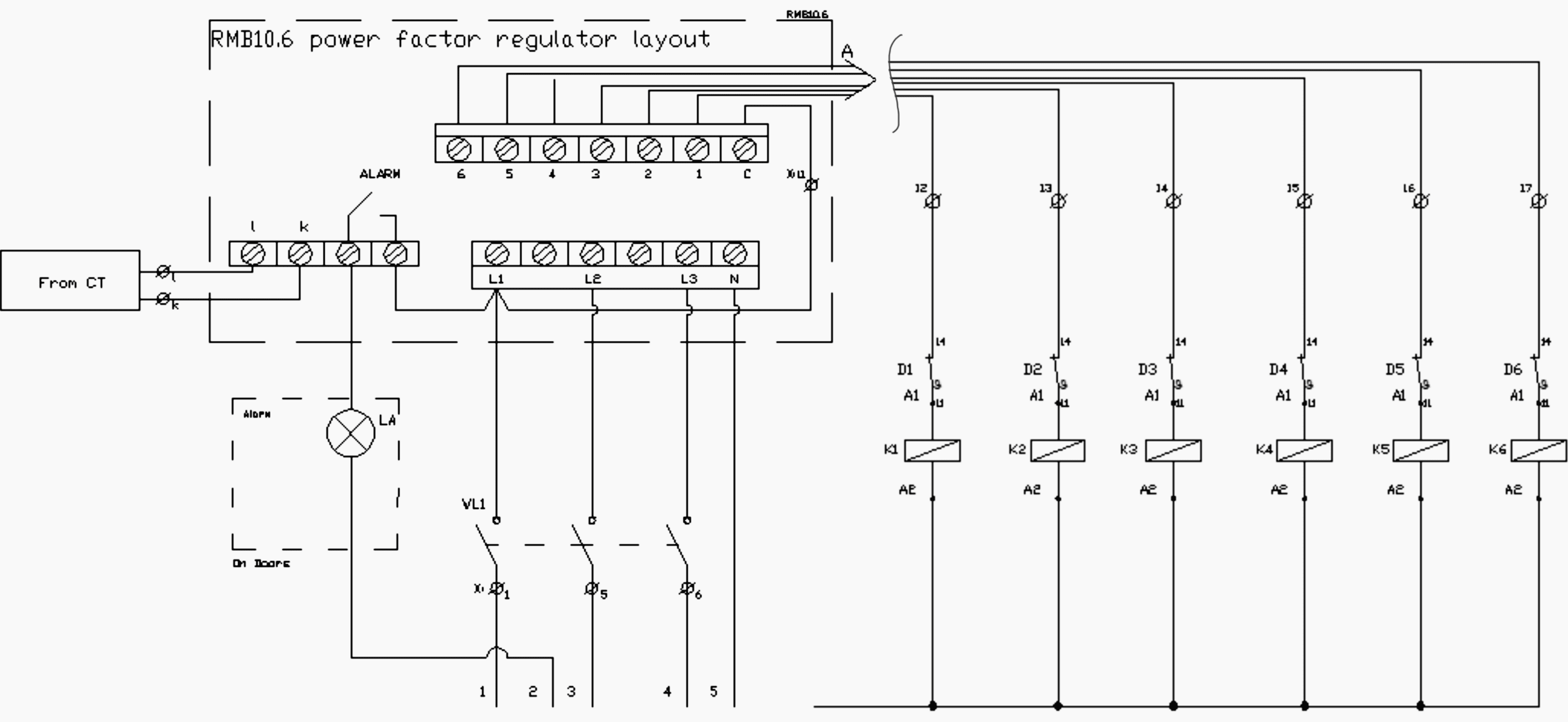
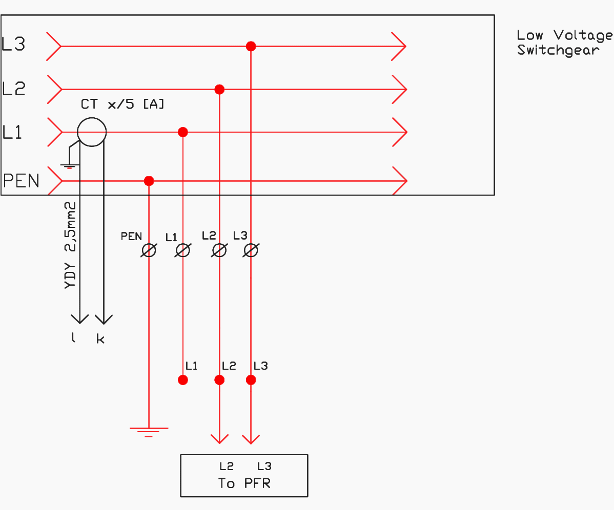
Step By Step Tutorial For Building Capacitor Bank And Reactive Power Compensation Panel Eep

Step By Step Tutorial For Building Capacitor Bank And Reactive Power Compensation Panel Eep

0 Response to "Capacitor Bank Working Principle Pdf"
Post a Comment